Heat Probe Pid Wiring Diagram
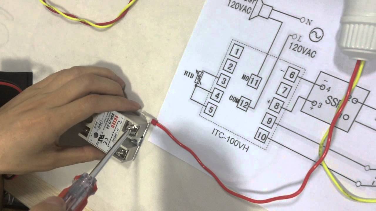
Probes ratio schematic thermocouples thermocouple How to connect and set pid temperature. controller? itc-100vh Pulse hpp probe thermistors distances
Heat water to exact temperature
Wiring sponsored links Pid temperature controller wiring diagram Heat transfer probe assembly: schematic of the heat flux sensor and
Probe flux
Wiring diagram pid controller temperature heatHeat water to exact temperature Wiring typicalController temperature pid itc connect set.
Heat water to exact temperaturePid temperature controller wiring diagram Schematic showing the heat pulse probe (hpp) with a total of 16Typical wiring diagram for pid temperature controller.
![Pid Temperature Controller Wiring Diagram](https://i2.wp.com/www.mikrora.com/wp-content/uploads/2018/12/enlkd_4.png)
Schematic drawing of the three probes used for the heat ratio method
.
.
![Heat water to exact temperature](https://i2.wp.com/waterheatertimer.org/images/wire-wh-wire-second-thermostat-PID-SSR.jpg)
![How to Connect and Set PID Temperature. Controller? ITC-100VH - YouTube](https://i.ytimg.com/vi/DZDkrR0Vhrc/maxresdefault.jpg)
![Heat water to exact temperature](https://i2.wp.com/waterheatertimer.org/images/wire-wh-wire-second-thermostat-PID.jpg)
![Heat transfer probe assembly: Schematic of the heat flux sensor and](https://i2.wp.com/www.researchgate.net/profile/Moses-Kagumba/publication/329510652/figure/fig4/AS:705134887723012@1545128666973/Heat-transfer-probe-assembly-Schematic-of-the-heat-flux-sensor-and-heater.png)
![Schematic showing the heat pulse probe (HPP) with a total of 16](https://i2.wp.com/www.researchgate.net/profile/Atac-Tuli/publication/228872797/figure/fig1/AS:393780101435393@1470895901175/Schematic-showing-the-heat-pulse-probe-HPP-with-a-total-of-16-thermistors-Distances_Q640.jpg)
![Pid Temperature Controller Wiring Diagram](https://i2.wp.com/www.mikrora.com/wp-content/uploads/2018/12/4mkwnky_7.jpg)
![Typical wiring diagram for PID temperature controller](https://i2.wp.com/hi-ip.com/image/data/texts/rexc100.jpg)